Forward
This is an over view of the potential for the QUENCHER in the ventilation market. It may seem detailed but the terms had to be defined as well as recent approaches. This can be exciting for all of us. Many gas steam processes, especially in powder collection systems, are candidates for the application of low cost gas mixing products as the Quencher supplied by Quality Air Management.
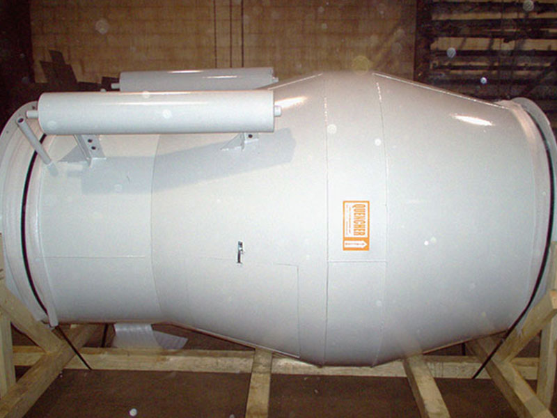
Note that embers & sparks get extinguished in the Quencher cell itself. Combusting material, such as paper or wood shavings, must be completely consumed within 4 duct diameters past the Quencher (where there is still enough turbulence) and taken the form of embers to be extinguished.
1) SPARK COOLING
Prevention of Sparks entering Solids separator (dust collector) equipment and starting fires
Definition: First we must define a spark. A spark is a piece of solid particulate which is completely oxidized and is at a temperature of 600 degrees F or over and which is above the ignition temperature of the powder being collected or above the ignition temperature of the filter elements.
Effects of sparks: Sparks can be carried along in the exhaust gas stream in laminar flow and will not cool off since cooling requires a difference in velocity between the gas and the spark being transported. Therefore, the spark will be carried into the solids separator and deposited on the filter element surface where it has a possibility of igniting the surface. If ignition occurs, the fire may spread and cause damage and produce harmful gases.
Response by the QUENCHER to sparks occurring in exhaust stream: The static blender converts the laminar flow to turbulent flow by thoroughly mixing the solid sparks with the gas stream, reducing the temperature of the sparks below the ignition temperatures of the filter media and the powder transported through the system.
2) HIGH TEMPERATURE COATING AND CUTTING PROCESSES
Originally a lot of these operations were performed by cutting with an acetylene torch to cut metal and with flame spray equipment which fed a wire into the flame of a gas torch to produce coating on various metallic and non-metallic surfaces.
The torch cuts were very coarse and had to be ground or put into other cold forming devices to make the parts usable. Often these cutting torches were applied to cutting up and reclaiming scrap. Most venting systems for torch cutting were vented into general ventilation and HVAC systems.
The flame spray equipment was limited to certain thicknesses and uniformity was such that on many parts subsequent grinding and smoothing operations were necessary. The coating produced was relatively coarse and the overspray was easily collected by low pressure drop wet powder collection devices. This avoided any requirements for mixing equipment.
The Advent of high temperature technologies was developed in the 1980-90’s decade; Lasers, plasma, and arc tools have been applied to the processes long dominated by gas torches and sprays. These new technology systems are much more intense, quicker, more accurate and more efficient than the old gas flame units. The temperatures developed in the devices are sufficient to vaporize metals and actually increase the temperature above this value. These systems can take sharp cuts and make intricate cuts, cut fine round holes replacing shears, drill with little or no need for grinding or finishing. They can process thick plate or light gauge sheet metal with the same machinery. They are guided by CNC controls for maximum flexibility. Applying these processes to spray systems is also very effective. The spray process must be explained prior to treating the ventilation of the high temperature cutting devices. These are the fastest growing fabrication processes in the world.
Spray systems; These systems were vented into relatively large gas and powder over spray collection hoods. They produced particles with a very strong attraction to the parts being coated. Some have theorized that the bonding is at the molecular level. When it strikes the surface to be coated it bonds to the surface as if the coating was integral with the object that is in the path of the spraying device. The coating is either fed into the device as a powder or a wire. The particulate overspray is relatively light in dust loading and the hood is vented to a dust powder collector. The wet collectors are not sufficiently effective to collect this much finer overspray. To develop sufficient collection efficiency, the overspray is vented to fabric or cartridge collecting device. The overspray is still attracted to any solid it gets near and will form a hard impermeable coating which can seal the surfaces of filter collection elements. These overspray particles though much finer than the sparks described above are carried along in ducts which have laminar flow. They must lose their attractive ability before they reach the dust collector / powder separator. If the powder spray is given sufficient time in flowing through the duct work, it will lose its coating ability. Typically the residence time of the dust flowing in the duct, is designed for about one second and sometimes up to 1.5 seconds. For a system running at 2400 feet per minute at least forty feet of duct work would be required between the hood and the collector. Most plants do not have the room for these long ducts. We theorize that a QUENCHER element could allow the reduction of this residence time by as much as 90% and be more predictable than the residence time especially as newer spray compounds are being developed.
Venting High Temperature Cutting Systems; Although the dust venting from the cutting processes do not have as high an attraction as the coating guns, the dust has the same problem. Residence times are often in the 0.5 to 0.7 seconds. Because the dust loadings are so low and the customer often removes the coated filter elements and vents outside, the emissions will be lower than most air pollution codes. However, if the dust could be collected and neutralized, the savings in heating and cooling costs could pay for a QUENCHER device in a month or so.
3) GAS MIXING IN POWDER SEPARATORS
QUENCHER gas mixing cooling of gas streams; Usually all gas streams are designed for the lowest pressure drop to save on power consumption in moving the gas from one point to another. This is accomplished by moving the gas in a flow pattern called “laminar flow”. In effect the gas stream is divided into cylinders that flow parallel in the duct work so that little or no mixing occurs between these cylinders within the walls of the ductwork. The other flow in a duct occurs when “turbulent flow” occurs. This is a violent mixing that occurs and will quadruple the pressure drop if it occurs in a length of duct. The gas follows the path of least resistance and naturally wants to revert to “laminar flow” when the disturbance or duct element, which produces the turbulent flow is removed. Both laminar and turbulent flow pressure drops are a function of the average velocity through the ducts. If we mix two gas streams flowing through well designed transitions that maintain laminar flow in the total stream, the resultant is that the gas streams will continue in the duct with little or no mixing of the combined gas streams. For instance if a gas stream at 300 degrees F is mixed with one at 100 degrees F, the resultant gas stream will be stratified and continue through the system with part of the flow at 100 degrees and part at 300 degrees. There might be a very narrow layer of the flow that mixes.
The proprietary QUENCHER design is such that the whole cross section of the duct produces an effective mixing with a minimum penalty of pressure drop by producing turbulent flow through the mixing element.
Temperature Lowering Processes for Solids Separation; Some powder collection gas streams use various means to cool the powder laden gas streams by mixing ambient outside air to reduce the gas temperature (and associated powder temperatures) to a level where a fabric media powder collector can separate the powder and gas for subsequent collection of the solids. A typical operation of this type is on a clinker cooler system in a cement plant. The gas temperature may vary from 200 to 900 degrees F. For operation of the powder separator collector, the temperature entering the collector must be lowered to less than 500 degrees, usually 475 degrees. This can be accomplished by blending the ambient gas stream with process gas. When this mixture is designed, the resultant gas streams often remain stratified with low and high temperature streams entering the powder separator collector. In the past there were various schemes to mix these streams such as special duct fittings. However with these schemes, the air was mixed at high velocities which produced wear on the high velocity mixing components. Placing a QUENCHER in the gas streams achieves the cooling and mixing at minimal wear because of their low velocity designs. This application combines the most difficult circumstances that are likely to be faced in this type of circumstance.
4) FIRES IN POWDER SEPARATING SYSTEMS, CAUSES OTHER THAN SPARKS
There can be solids and liquids in exhaust systems that can cause fires in powder separation equipment.
Solids that are still burning when they enter the exhaust system; These can possibly develop into an explosion front entering the exhaust system. However more likely they will have the appearance of a spark in the exhaust system. A good example of this phenomenon is the collection of burning particles of paper usually strips. The paper provides both the oxygen and fuel to continue the burning process. The mixing process in the QUENCHER element may not cool the burning debris to lower it below the ignition temperature of the powder or filter media. The solution is to completely oxidize the solids before it enters the collection device (dust collector) and associated spark cooler. In that case multiple QUENCHERs may speed up the oxidation and may be a field for future consideration in expanding the QUENCHER market. Another approach might be to install sprays of water prior to the blender and to modify the blender to separate droplets from the cooled gas stream. We can modify the blender designs to make them water droplet separators. (This was the approach taken at Mueller Brass. That service report confirms the efficacy of this approach.)
Spontaneous Combustion; Some metallic and other compounds will oxidize when mixed at room temperatures. This process is well documented when we hear of fires that are smoldering after a fire that suddenly break out into a full scale fire. Catalytic combustion where oxidation takes place between 120 and 300 degrees F is another example of this phenomenon. These fires can be prevented with a combination of QUENCHER and control changes to the powder dust collector operating and will be covered in a separate report in the future.
Explosions; Explosions in the exhaust system can and do trigger fires in collectors. The combustion produces a sustainable conflagration which travels through the ducts at very high speeds. While a QUENCHER mixer can reduce the effect of this flame front by lowering the intensity, the QUENCHER cannot be an approach to prevent explosions.
5) QUENCHER AS PART OF EVAPORATIVE COOLING SYSTEM FOR WET AND DRY POWDER SEPARATORS (DUST COLLECTORS)
In venting furnaces for metallurgical processes; Typically, these furnaces will exhaust at temperatures between 900 and 1800 degrees F. They are vented to either wet collection equipment or through fabric filter element powder collection equipment. As the gas stream enters
Wet Collectors; Wet collection equipment are called air washers or gas scrubbers. These collectors are most effective if the exhaust stream entering the collection device is close to 100% relative humidity, typically 120 to 160 degrees. The temperature is usually reduced by coarse water sprays. The humidification efficiency is usually 80 to 85 percent. The efficiency of the humidifier has a drastic effect on the collection efficiency of the wet collector. The addition of a QUENCHER will increase this humidification efficiency to over 95 per cent. This simple addition might improve collection efficiency to meeting the existing air pollution codes.
Dry Collectors; Many Industrial Processes such as insulation processes or making Mineral, fiberglass insulation, perlite processes develop the process in a furnace. Then the exhaust stream from the furnaces, containing the insulating batts or powder, must be separated from the exhaust stream. The separation device is a dry powder/dust collector. Collecting in a wet form will not produce a usable type of product. Normally the method of cooling is with an evaporate cooling tower that forms a wet cyclonic action from top to bottom. The purpose is to cool the dust laden gas stream to a temperature below 400 degrees F and with dew point temperatures that avoid condensing on the cooling tower walls, as the process temperature rises and falls. The humidifying is controlled to maintain the proper relationship of wet and dry bulb as determined by system operating parameters.. Fogging nozzles and the control of the water spray rates is used to control the outlet temperature and humidification. The controls are complex because of the relatively low velocity of gases in the tower.
QUENCHER adaptation; The cooling tower would be replaced by a spray mounted in the high temperature ductwork. The QUENCHER would cause the water to evaporate completely and the spray would be increased by the temperature measured at the entrance to the powder collector. This would be more effective and reliable than the big bulky cooling towers which try to control the residence time of the droplets as they evaporate.
CONCLUSION
Every metal working, foundry, Metal processing, Cement and woodworking plant is a candidate for QUENCHER Technology.